Step 0 - Compiling and Hands-on
Container image
Start a jupyter lab environment (see Running Jupyter Lab)
Compiling the firmware
As a prerequisite for all remaining notebooks, you have to compile the firmware that will run in the M3 sensors.
3 OS are available:
Nullrdc: always on CSMA
Contikimac: LPL (low power listening)
TSCH: Time slotted channel hopping
For 2 types of nodes (more details see figure below):
Border Router: the gateway between the radio network and the outside world.
CoAP server (sensor): the IoT sensor.
A notebook is available to compile the firmwares, please open the notebook available at: setup/compile-firmware.ipynb.
At the end of this step you must have 3 folders (contikimac, nullrdc and tsch) under data/firmware/custom, each containing 2 images (border-router.iotlab-m3 and er-example-server.iotlab-m3).
Hands-on
This hands-on shows how to run an experiment directly from Grid’5000 and FIT/IoT-LAB frontends. It presents the main commands that you use to reserve, deploy and run applications on both platforms. For simplicity, we use the container image to access the respective frontends through ssh, but you may run the ssh commands directly from your terminal.
Objective: reserve the nodes and verify connectivity and latency time between platforms.
You’ll need:
Grid5000: 1 node
FIT/IoT-LAB: 2 M3 nodes (1 border router and 1 sensor)
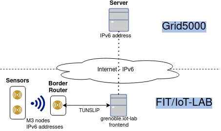
The image depicts the environment we’ll create in our experiment. It is characterized by:
IPv6 connectivity: nodes have global, valid IPv6 addresses.
Radio interface: between M3 sensor and M3 border router.
Serial interface: connects the border router to the frontend, and consequently, the Internet.
Note
Due to firewall policy in Grid’5000, incoming traffic to nodes in Grid’5000 are filtered out. However, it’s possible to start the communication from Grid’5000 to FIT/IoT-LAB.
To start, open a new terminal to run the commands below (File->New->Terminal).
IoT-LAB setup
You can check the Grenoble’s topology at: https://www.iot-lab.info/docs/deployment/grenoble/.
This tutorial is available at: https://www.iot-lab.info/legacy/tutorials/understand-ipv6-subnetting-on-the-fit-iot-lab-testbed/index.html.
More details about CLI tools are available at: - https://www.iot-lab.info/docs/tools/cli/
Copy firmware and access the frontend
export FIT_USERNAME=<username>
scp -r data/firmware/custom/ $FIT_USERNAME@grenoble.iot-lab.info:rsd-hackathon/
ssh $FIT_USERNAME@grenoble.iot-lab.info
Note that you could run the “iotlab-*” commands directly from the container image, but we opt here to run everything in the FIT/IoT-LAB frontend.
Reserve nodes (2 M3 nodes) and wait submission to be ready.
iotlab-experiment submit -n rsd-hackathon -d 60 -l 2,archi=m3:at86rf231+site=grenoble
iotlab-experiment wait
Get the list of nodes available for your experiment. Select one to be the border router and another one to be the sensor.
Note that you’re free to choose the nodes as you want.
iotlab-experiment get -n
Flash the firmware on each node.
iotlab-node --flash rsd-hackathon/contikimac/border-router.iotlab-m3 -l grenoble,m3,<br_id>
iotlab-node --flash rsd-hackathon/contikimac/er-example-server.iotlab-m3 -l grenoble,m3,<sensor_id>
# e.g. iotlab-node --flash rsd-hackathon/contikimac/border-router.iotlab-m3 -l grenoble,m3,10
Create the IPv6 network.
Tunslip daemon will act as a router, forwarding the IPv6 packets between border router and the external network.
You need to select an available IPv6 prefix for the Grenoble site (https://www.iot-lab.info/legacy/tutorials/understand-ipv6-subnetting-on-the-fit-iot-lab-testbed/index.html).
Warning
Each group needs to select a different prefix.
To avoid conflicts, use the IPv6 network assigned to you in https://gitlab.inria.fr/rsdschool21/lab/-/blob/master/setup/rsd2021hack.csv
sudo tunslip6.py -v2 -L -a <border router> -p 20000 <IPv6 preffix,> > tunslip.output 2>&1 &
# e.g.: sudo tunslip6.py -v2 -L -a m3-10 -p 20000 2001:660:5307:3100::1/64 > tunslip.output 2>&1 &
Check the output of tunslip command.
cat tunslip.output | grep -A5 "Server IPv6 addresses"
Note the IPv6 address of our border router (BR).
0001.306 Server IPv6 addresses:
0001.308  2001:660:5307:3100::8772
0001.308  fe80::8772
0004.078 Upper layer checksum len: 76 from: 40
0006.186 IPv6 packet received from fe80::9971 to fe80::8772
0006.187 icmp6_input: length 74 type: 155
The border router’s IPv6 address starts with the prefix chosen before and the last 4 digits are defined by the BR’s identifier.
You can request the border router for a list of sensors available.
lynx -dump http://[<BR IPv6 address>]
# e.g. lynx --dump http://[2001:660:5307:3100::8772]
Below Neighbors we have the 4 digits that form the suffix for each sensor.
The IPv6 address will be formed by:
prefix + suffix: e.g.: 2001:660:5307:3100:: + 9982 = 2001:660:5307:3100::9982
More info: https://github.com/iot-lab/iot-lab/wiki/Get-M3-and-A8-M3-nodes-uid—ipv6-address-match
Check the latency to the border router and sensor.
Note that the ping to the border router uses only the serial interface.
ping6 -c5 <BR IPv6 address>
# e.g ping6 -c5 2001:660:5307:3100::8772
On the other hand, the communication with the sensor will use the radio interface.
ping6 -c5 <sensor IPv6 address>
# e.g. ping6 -c5 2001:660:5307:3100::9971
Grid’5000 setup
Open another terminal (File->New->Terminal).
At Grid’5000 site, we only need to reserve 1 node and enable IPv6 in it. It’ll be used to measure the latency and verify the path to the M3 nodes.
Access the Grenoble frontend node.
ssh <username>@grenoble.grid5000.fr
Reserve 1 node in iterative mode.
oarsub -I
Enable IPv6 on it.
sudo-g5k dhclient -6 br0
Repeat ping command to border router and sensor, but from the Grid’5000 node now.
ping6 -c5 <BR IPv6 address>
ping6 -c5 <sensor IPv6 address>
Run traceroute to verify the path.
traceroute6 -c5 <BR IPv6 address>
traceroute6 -c5 <sensor IPv6 address>
Note the difference between delays from Grid’5000 to:
border router
sensor
May you verify where is the major network latency?
Cleanup
Stop experiment in IoT-LAB running this command on IoT-LAB frontend.
iotlab-experiment stop
In Grid’5000, since we use an iterative job, it is automatically finished when you close the terminal session.